
Vous êtes le 1201e visiteur
NB : Ce document issu de mon rapport de fin d'étude fut initialement rédigé en anglais. Une version française sear prochainement disponible
OSPF protocol allows the definition of areas to group networks and/or hosts.
Each area thus defined will run a separate copy of the routing protocol. It
means that the local topological database will not be propagated to other
areas.
Then is defined the notion of backbone. It consists of all the network and
routers not fully included in an area. Actually it is the network binding
all the area together and its own topology is also invisible to each of the
area.
Therefore a few new terms needs to be defined :
OSPF is able to compute routes according to the IP TOS
field. Different path costs can be configured depending on TOS value. Then the
route to a single destination can vary depending on the type of service carried.
A cost for TOS 0 must always be specified. In case no proper route can be found
for a particular TOS, the TOS 0 route would be used.
Each area border summarizes the topological information of its
attached networks and then provides backbone routers (and then other area border
routers) with this information.
Meanwhile it receives the summaries from other areas. It can then compute paths
to all destinations out of its attached areas and finally advertise them in
its attached areas
As a result internal routers can choose the best route (and then the best area
border router) when forwarding traffic to other areas.
Each router receiving information regarding other AS can
flood them throughout the AS. Every participating routers should know the route
to AS boundary routers. So they can calculate routes to destinations out of
the AS.
In fact OSPF support two types of external metrics :
OSPF uses adjacency to determine which routers are involved
in routing packets within the area. Protocol information (link state advertisement)
will only be exchanged between those routers. Afterwards topological database
will be synchronized between any router pairs forming an adjacency.
Adjacencies are built up through the use of the Hello Protocol. When a router
comes up it sends Hello packet to all his neighbouring routers. On a broadcast
network, it may use the multicast address AllSPFRouters (224.0.0.5). On non-broadcast
networks it first needs to know the list of routers in the area.
On multi access networks the Hello protocol is also used to determine the Designated
and the Backup Designated Router.
Thus routers discover their neighbours. They can also list the routers with
whom a two-way communication was established by examining received Hello packets
(their own IP address will appear in the remote router’s neighbours list). Those
routers are promoted to the level of 2-Way routers.
Then the router can decide if an adjacency if should be built with each 2-Way
routers, that is when :
fig 2 - The standard OSPF header
Version : Version number of OSPF protocol. Currently version
2. 1-byte
Type : Type of the OSPF packet. 1-byte
|
Type |
Description |
|
1 |
Hello |
|
2 |
Database description |
|
3 |
Link State Request |
|
4 |
Link State Update |
|
5 |
Link State Acknowledgment |
Table1 - Type of OSPF Packet
Packet length : Length of the total OSPF packet — 2 bytes.
Router ID : Identifying of the source router — 4 bytes.
Area ID : Identifying the area the packet belongs to — 4 bytes.
Checksum : The standard IP checksum of the entire contents of the packet, excluding
the 64-bit authentication field. This checksum is calculated as the 16-bit one's
complement of the one's complement sum of all the 16-bit words in the packet,
excepting the authentication field. If the packet's length is not an integral
number of 16-bit words, the packet is padded with a byte of zero before checksumming
– 2 bytes.
Autype : Type of authentication. — 2 bytes.
|
AuType |
Description |
|
0 |
No authentication |
|
1 |
Simple password |
|
All others |
Reserved for assignment by the IANA (iana@ISI.EDU) |
Table2 - Type of OSPF Authentication
Authentication : 8 bytes
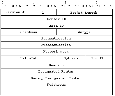
fig 3 - The Hello packet
HelloInt : number of seconds before reemitting a
hello packet.
Rtr Pri : Router’s priority used when electing designated router.
Deadint : The number of seconds before declaring a silent router down.
Designated router : Designated router from the advisor point of view.
Backup Designated Router : Backup designated router from the advisor point of
view.
Neighbour : List of router IDs from whom the router has received Hello packet
in the last Deadint seconds.
Options : Optional capabilities of the router.
![]()
fig 4 - The Option field
T-bit :This describes the router's TOS capability. If the T-bit is reset, then the router supports only a single TOS (TOS 0). Such a router is also said to be incapable of TOS-routing. The absence of the T-bit in a router links advertisement causes the router to be skipped when building a non-zero TOS shortest-path tree. In other words, routers incapable of TOS routing will be avoided as much as possible when forwarding data traffic requesting a non-zero TOS. The absence of the T-bit in a summary link advertisement or an AS external link advertisement indicates that the advertisement is describing a TOS 0 route only.
E-bit : AS external link advertisements are not flooded into/through OSPF stub areas. The E-bit ensures that all members of a stub area agree on that area's configuration. The E-bit is meaningful only in OSPF Hello packets. When the E-bit is reset in the Hello packet sent out a particular interface, it means that the router will neither send nor receive AS external link state advertisements on that interface (in other words, the interface connects to a stub area). Two routers will not become neighbours unless they agree on the state of the E-bit.
The designated and backup designated routers
are supposed to be those routers having the highest priority. In case of a tie
the highest Router_ID is chosen (See 1.1). However if a designated router has
already been elected when a new router with a higher priority is connected to
the network, then this new router does not become the new designated router.
Initially the corresponding fields are set to 0.0.0.0 to signify that no designated
router have been chosen yet.
The designated router is in charge of advertising the list of all routers currently
attached to the network. As adjacent to all other routers in the network it
is the centre of the synchronization process.
The backup designated router is provided to reduce transition time, and then
loss of network connectivity, if the designated router happens to fail. This
router obviates the need to compute adjacencies again. Yet it does not generate
network link advertisement to reduce database size.
As soon as an adjacency is about to be brought up, the two routers making this adjacency begins trying to synchronize their database. During the exchange the router experience several states
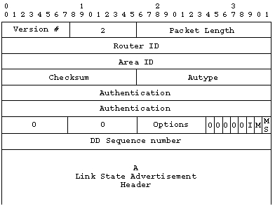
fig 5 - Database description paket
0 fields : reserved. Must be kept to 0
I-bit : Init bit. When set to 1, it indicates this packet is the first in the
sequence of database descriptions.
M-bit : More Bit. When set to 1 it, it indicates that more database descriptions
follow.
MS-bit : The Master/Slave bit. When set to 1, it indicates the router is the
master. When set to 0, it indicates the router is the slave.
DD : Sequence number. Identify uniquely each database description packets during
the complete database description.
Rest of the packet : Made of link state advertisements in the topological database.
This information allows the receiving router to ask later for specified link
state advertisements. This list may be incomplete.
Database description packets are accepted only up from the ExStart level.
At the ExStart level, the Options field from the neighbouring router is recorded and the packet treated if :
The MS bit must remain consistent during the exchange. Otherwise a Seq Number Mismatch is generated. Assuming this condition is satisfied :
Master packets, which are not acknowledged, are repeated.
The entire database has been sent and received and the only packets accepted are repeated packets. Routers may notice part of their database is no more up to date and may request for more recent information through the use of link state request packet.
All link state advertisement begins with a common 20 bytes header.
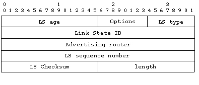
fig 6 - Link State Advertisement Header
LS age : Time in seconds since the link advertisement was generated
Options: Optional capabilities supported by the described portion of the routing
domain
LS type : Type of the link state advertisement
| LS Type |
Description |
|
1 |
Router links |
| 2 |
Network links |
| 3 |
Summary link (IP network) |
| 4 |
Summary link (ASBR) |
| 5 |
AS external link |
Table 3 - Type of link state advertisement
Link State ID : Identifies the portion of the network described
by the link advertisement.
Advertising router : The router ID of the router, which has generated the link
advertisement.
LS sequence number : Identifies this particular advertisement in a sequence.
LS checksum : The Fletcher checksum of the complete link advertisement.
Length : Total length in bytes of the link advertisement.
This is the OSPF type 3 packet. It is accepted only by
routers in Exchange, Loading or Full state.
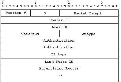
fig 7 - Link State request packet
LS type, link State ID and Advertising router uniquely define the advertisement but not its instance. Therefore this request is always understood as a request for the most recent instance available.
These are OSPF type 4 packets. They implement the flooding
of Link State advertisements. Each of these packets carries the update one hop
further.
They are multicasted when possible and always acknowledge. In case a retransmission
is necessary it is always done in unicast.
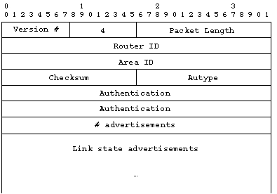
fig 8 - Link State Update packet
#advertisements : Number of link state advertisements included in this update
These are type 5 OSPF packets provided to make link advertisements reliable. Their format is similar to data description packet.
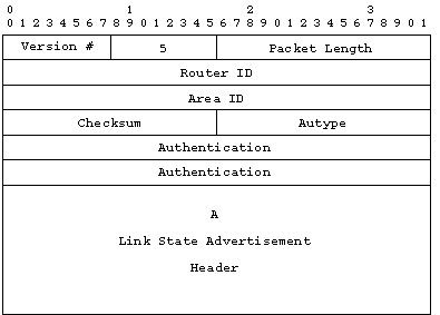
fig 9 - Link State Acknowledgement packet
These are type 1 link state advertisements.
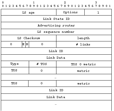
fig 10 - Router Link State Advertisement
bit E : When set the router is an AS boundary router.
bit B : When set the router is a area border router.
#links : The number of links describe in this advertisement. This must be the
total collection of router links to the area.
Type : Defines the type of the router link. Host route are considered as route
to a stub network with a 0xFFFFFFFF mask.
| Type |
Description |
| 1 |
Point to point connection to an other router |
| 2 |
Connection to a transit network |
| 3 |
Connection to a stub network |
| 4 |
Virtual link |
Table4 - Type of OSPF link
Link ID : Identifies the object the router is connected to. Its value depend on the type of link
| Type |
Link ID |
| 1 |
Neighbouring router's ID |
| 2 |
IP address of Designated Router |
| 3 |
IP network/subnet number |
| 4 |
Neighbouring router's ID |
Table5 - Type of OSPF link ID
Link Data : Content depends on the link type. For stub
network, it is the network mask. For other link it is the IP address of the
router’s interface.
#metrics : The number of TOS metrics given for this link, not counting the required
metrics for TOS 0.
TOS : IP type of service the metric refers to (D=delay, T=throughput, R=reliability).
They must be sorted by increasing number order.
| Type |
D |
T |
R |
| 0 |
0 |
0 |
0 |
| 4 |
0 |
0 |
1 |
| 8 |
0 |
1 |
0 |
| 12 |
0 |
1 |
1 |
16 |
1 |
0 |
0 |
20 |
1 |
0 |
1 |
24 |
1 |
1 |
0 |
28 |
1 |
1 |
1 |
Table6 - Representing TOS in OSPF
metric : The cost of using this outbound router link for the specified TOS.
These are type 2 link state advertisements. They are originated by the designated router for all transit network in the area and gives the list of all routers attached to the network.
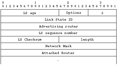
fig 11 - Network Link State Advertisement
The link State ID corresponds here to the network’s designated router’s IP address.
Network mask : The IP address mask for the network.
Attached router : Router ID of all routers in the area and which are adjacent
to the designated router, plus the designated router itself.
These are type 3 and type 4 link state advertisements.
They are originated by area border routers. There is one link state per destination
known to the router in the AS but outside the area.
Type 3 are used for networks, whereas type 4 are used for AS boundary routers.
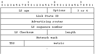
fig 12 - Summary Link State Advertisement
Link State ID : Either the IP network address or the AS boundary
router’s Router ID.
Network mask : IP network mask for type 3 link state. Must be set to 0 for type
4.
TOS : Type of service concerned by the following metrics.
metrics : Cost of this route.
These type 5 link state advertisement are generated by
AS boundary routers. A separate advertisement is made for each destination known
of the router outside the AS.
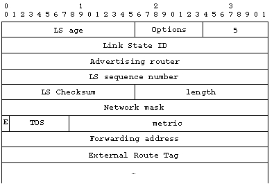
fig 13 - AS external Link State Advertisement
Link state ID : Here the IP address of the network advertised.
Network mask : IP network mask.
TOS : Type of service concerned by the following information.
bit E : Type of external metric used (see 2.1.4).
metric : Cost of the route for the specified TOS.
Forwarding address : Data traffic for the advertised destination will be forwarded
to the specified IP address. If it is set to 0.0.0.0, data traffic will be forwarded
to the responsible AS boundary router.
External route
flag : A 32-bit field attached to each external routes. It is not used by OSPF
protocol itself. But may be used by AS boundary routers to communicate information.
It is not defined by the OSPF specification.
The process can be divided in several step.
The present routing table is invalidated. It is saved for comparison and a new table is built from scratch. This happens each time an upgrade in the topological database occurs.
The intra-area routes are calculates through the shortest path tree algorithm. First only links between routers and transit network are considered. Stub networks are only incorporated at the end as leafs of the tree.
The inter-area routes are calculated for all the area on which the router has no interface connected. This is done by examining summery link advertisements and using the shortest path tree algorithm.
For each entry whose next hop is a virtual link, a physical next hop is computed.
Routes to external destination are calculated through the examination of AS external link advertisements.
These five steps will be executed for each IP type of service supported. Then inter-area summary links advertisements may be generated.
The shortest path tree is calculated with the router itself
as root and the Dijkstra algorithm.
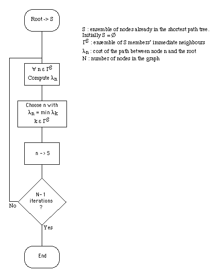
fig 14 - Shortest Path Tree algorithmThe routing table
The routing table includes :
When an IP packet is to be routed, the most specific match in the routing table is used. Therefore the matches are pruned using the following criteria (in this order) :
1) the most suitable path type (e.g. if the destination
may belong either to the local area or to an other, intra area path type is
preferred).
2) the most restrictive address mask
3) possibly filter on the IP type of service
If multiple paths remain, they are used indifferently.